
The AFFF Transition Goes Beyond Foam Replacement
Across Europe, the transition away from PFAS-containing firefighting foams is moving from preparation to implementation.
Commission Regulation (EU) 2025/1988 introduces Entry 82 into Annex XVII of REACH, establishing restrictions on PFAS in firefighting foams together with transition periods and specific requirements for continued uses.
For many operators, the most visible part of this transition is straightforward: replace existing AFFF stocks with fluorine-free firefighting foam (F3).
But changing the foam is not necessarily the end of the PFAS problem.
Fire suppression systems that have contained fluorinated foams for years, or even decades, can retain PFAS residues within tanks, pipework, pumps, valves, seals and other components. Cleaning those systems can, in turn, generate PFAS-containing wastewater requiring its own treatment strategy.
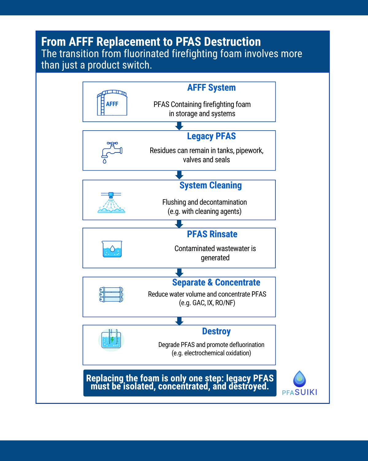
The AFFF transition therefore needs to be considered as a chain:
Foam inventory → AFFF removal → System decontamination → Rinsate management → PFAS treatment
Understanding each step is becoming increasingly important for facility managers, EHS teams and fire safety professionals planning the transition.
REACH Entry 82: What Is Changing?
Commission Regulation (EU) 2025/1988 establishes a general restriction of 1 mg/L for the sum of all PFAS in firefighting foams, with phased implementation dates and derogations for specific applications.
The regulation also goes beyond the composition of the firefighting foam itself.
For certain continued uses of PFAS-containing firefighting foams, requirements applicable from 23 October 2026 include measures to minimize releases and a site-specific PFAS-containing firefighting foams management plan.
Depending on the applicable use, the management plan addresses areas such as:
- conditions and volumes of PFAS-containing firefighting foam use;
- collection and treatment measures;
- equipment cleaning and maintenance;
- management of accidental releases; and
- the strategy for transitioning toward PFAS-free alternatives.
This makes the transition more than a procurement exercise. Operators need to understand where PFAS are present, how existing systems will be cleaned and what will happen to the PFAS-containing waste streams generated in the process.
The Rebound Effect: PFAS Can Remain in Existing Infrastructure
One of the less visible challenges occurs inside the fire suppression system itself.
AFFF formulations contain fluorinated surfactants designed to interact strongly with interfaces. Following long-term use, PFAS residues can remain associated with internal surfaces and components throughout a fire suppression network.
This can include:
storage tanks · pipework · proportioning equipment · pumps · valves · seals · hoses · discharge components
Simply draining an AFFF system and replacing the foam may therefore not remove all residual PFAS.
When the cleaned system is subsequently filled with water or fluorine-free foam, residual PFAS can desorb from surfaces and migrate back into the liquid phase, a phenomenon often referred to as the rebound effect.
Importantly, this challenge is explicitly recognized in the European regulation.
The Regulation Recognizes Residual PFAS
REACH Entry 82 provides a specific derogation for fluorine-free firefighting foam placed into equipment that previously contained PFAS-containing foam and has been cleaned according to best available techniques.
In this situation, the regulation provides a limit of 50 mg/L for the sum of all PFAS, recognizing that residual PFAS may remain in equipment and subsequently migrate into newly installed fluorine-free foam.
The European Commission specifically connects this provision to the developing understanding of the rebound effect and requires the derogation to be reviewed.
This distinction is important: transitioning to F3 and decontaminating the existing fire suppression infrastructure are connected, but technically different, challenges.
From Decontamination to a New PFAS Stream: The Rinsate Challenge
Removing residual PFAS from a fire suppression system means transferring those contaminants somewhere else.
Depending on the system configuration and cleaning protocol, decontamination may involve repeated flushing, circulation and the use of suitable cleaning agents. This can generate substantial volumes of PFAS-containing rinsate.
The contamination has therefore not disappeared. It has moved:
Legacy infrastructure → Cleaning process → PFAS-containing wastewater
The characteristics of this wastewater can also differ considerably from the original AFFF concentrate. PFAS concentration and composition, cleaning agents, dissolved organic matter, salts and other matrix components can all influence the appropriate treatment pathway.
This is why rinsate management should ideally be considered before the cleaning campaign begins, not after thousands of liters of contaminated water have already been collected.
Questions such as storage capacity, sampling, characterization, transport and treatment should form part of the transition strategy.
REACH also Addresses the Wastewater
This is an important but sometimes overlooked element of Entry 82.
The regulation addresses PFAS-containing waste, including wastewater, originating from the use and cleaning of firefighting foam systems.
Where technically and practically possible, these waste streams should be collected separately and handled for adequate treatment so that their PFAS content is destroyed or irreversibly transformed.
This creates an important distinction between removing PFAS from water and destroying PFAS.
For operators developing a rinsate management strategy, the relevant question is therefore not only:
“Can we remove PFAS from this wastewater?”
but also:
“Where does the PFAS go next?”
From Separation to Destruction: Managing the Rinsate Treatment Train
Established water-treatment technologies can play an important role in managing PFAS-containing rinsate.
Granular Activated Carbon (GAC) can adsorb PFAS from the liquid phase, particularly certain longer-chain compounds. Performance, however, depends strongly on the water matrix and the presence of competing organic constituents.
Ion Exchange (IX) uses selective resins to capture ionic PFAS and can provide high treatment capacities depending on PFAS composition and matrix conditions. The resulting spent resin or regenerant still requires appropriate downstream management.
Reverse Osmosis and Nanofiltration (RO/NF) can achieve significant separation of PFAS from water, producing a treated permeate and a lower-volume PFAS-rich concentrate.
These technologies perform an important function: they separate and concentrate PFAS.
But separation alone does not destroy the PFAS molecules. Instead, the PFAS mass is transferred into another phase, such as spent adsorbent, regenerant or membrane concentrate.
This is why separation and destruction should not necessarily be viewed as competing treatment approaches.
For many water streams, they can be complementary.
Concentrate First, Destroy Second
For large-volume PFAS-containing rinsates, a treatment train can be designed around a simple principle:
- Separate → 2. Concentrate → 3. Destroy
Upstream separation reduces the volume requiring destructive treatment. The resulting PFAS-rich stream can then become the feed for a destruction technology.
This can significantly change the engineering challenge. Rather than applying an energy-intensive destruction process to the entire wastewater volume, treatment can focus on a smaller, more concentrated PFAS stream.
Electrochemical Oxidation as a Destruction Step
Electrochemical oxidation (EO) is one technology being developed for this role.
In an electrochemical reactor, electrical energy drives oxidation reactions at or near the electrode surface. Under suitable operating conditions, these reactions can initiate degradation of PFAS molecules and ultimately promote cleavage of the highly stable carbon-fluorine structure and defluorination.
For AFFF-related water streams, however, PFAS concentration alone does not determine treatment performance.
The water matrix matters.
Cleaning agents, organic constituents, chloride, sulfate, conductivity and other components can influence electrochemical reaction pathways, energy demand and the potential formation of unwanted byproducts.
Effective electrochemical treatment therefore requires more than applying a high current to contaminated water. Operating parameters such as current density, flow rate, treatment time and electrode configuration need to be considered alongside the specific water chemistry.
The objective is to identify an operating window that achieves PFAS degradation and defluorination while controlling energy consumption and relevant byproduct formation.
This is particularly important for real AFFF rinsates, which can be substantially more complex than synthetic PFAS solutions used in laboratory testing.
Planning the AFFF Transition: Five Questions for Facility Managers
A robust transition strategy starts before the existing foam is drained. Facility and EHS teams should consider five questions:
1. What PFAS-containing materials are currently on site? Document foam stocks as well as the systems, tanks and equipment that have historically contained fluorinated firefighting foam.
2. How will the existing infrastructure be decontaminated? Define a cleaning protocol appropriate for the system rather than assuming that draining and a single water flush will remove residual PFAS.
3. How will cleaning wastewater be contained? Plan sufficient storage and containment for rinsate before cleaning begins, including contingency capacity where appropriate.
4. How will the rinsate be characterized? Understanding PFAS composition and concentration together with relevant matrix parameters is essential for selecting an appropriate treatment pathway.
5. What ultimately happens to the PFAS? When comparing treatment options, distinguish between technologies that separate PFAS from water and those intended to destroy or irreversibly transform the PFAS mass.
From Foam Replacement to PFAS Management
The transition from AFFF to fluorine-free firefighting foam is an important milestone, but it should not be viewed as an isolated purchasing decision.
For facilities with legacy AFFF systems, the transition can involve three interconnected technical challenges:
removing existing foam, managing residual PFAS within the infrastructure, and determining an appropriate treatment pathway for the wastewater generated during cleaning.
REACH Entry 82 brings these issues together. Alongside restrictions on PFAS-containing firefighting foams, the regulation addresses equipment cleaning, PFAS-containing waste and wastewater, and adequate treatment aimed at destroying or irreversibly transforming PFAS where technically and practically possible.
For facility managers and EHS teams, the practical question is therefore no longer only:
“What foam will replace AFFF?”
It is also:
“What happens to the PFAS already in our system?”
At PFASuiki, we work with industrial partners to characterize PFAS-containing water streams and evaluate treatment and destruction pathways for concentrated PFAS wastewaters, including AFFF-related streams.